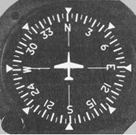
| Azimuth Heading Indicator
The heading indicator shown in Figure 4-39 is representative of the
instruments found in the more recent general aviation aircraft. This instrument
is a refinement of the older vacuum-driven heading indicator and is considered
easier to interpret. Figure 4-39. Azimuth directional gyro.
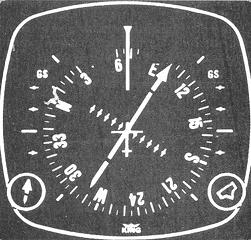
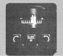
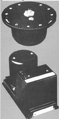
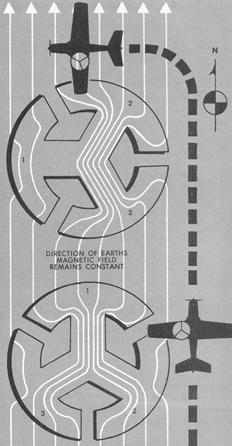
Remote Indicating Compass Remote indicating compasses have been developed to compensate for the errors and to reduce the limitations of the older type heading indicators. The pictorial navigation indicator and the slaving control and compensator unit, the two panel mounted components of a typical system, are shown in Figure 4-40. The pictorial navigation indicator is commonly referred to as a horizontal situation indicator (HSI), which is described on page 53. The heading indicator of the pictorial navigation indicator is a remote indicating compass. The slaving control and compensator unit has a pushbutton that provides the pilot a means of selecting either the "'slaved gyro" or "free gyro" mode. The slaving control and compensator unit also has a slaving meter and two manual heading drive buttons. The slaving meter indicates the difference between the displayed heading and the magnetic heading. A right deflection indicates a clockwise error of the compass card; a left deflection indicates a counterclockwise error. Whenever the aircraft is in a turn and the card rotates, the slaving meter will show a full deflection to one side or the other. When the system is in "free gyro" mode, the compass card may be adjusted by depressing the appropriate heading drive button. The magnetic slaving transmitter and directional gyro unit are illustrated in Figure 4-41. The magnetic slaving transmitter is mounted remotely, usually in a wingtip, to eliminate the possibility of magnetic interference. It contains the flux valve which is the direction sensing device of the system. Its operation is diagrammatically illustrated in Figure 4-42. The flux valve picks up the lines of force concentrated in any one spoke segment of the unit. Note in the illustration how the concentration of lines of flux change from number 1 to numbers 2 and 3 as the aircraft changes heading from north to west. This concentration of lines of magnetic force, after being amplified, is relayed to the directional gyro unit, which is also remotely mounted. These signals operate a torque motor in the directional gyro unit. The torque motor precesses the gyro unit until it is aligned with the transmitter signal. The magnetic slaving transmitter is connected electrically to the heading indicator of the pictorial navigation indicator on the instrument panel. Figure 4-40. Pictorial navigation indicator; slaving control and compensator unit.
There are a number of designs of the remote indicating compass, therefore only basic features of the system are covered here. As an instrument pilot, you should become familiar with the characteristics of the equipment in your aircraft. Figure 4-41. Magnetic slaving transmitter and directional gyro unit.
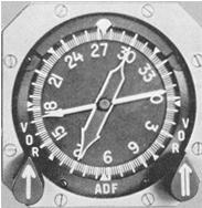
Radio Magnetic Indicator (RMI) The radio magnetic indicator, or RMI, is beginning to appear on the instrument panels of modern general aviation aircraft. This instrument, shown in Figure 4-43, consists of a rotating compass card, a double-barred bearing indicator, and a single-barred bearing indicator. The compass card, actuated by the aircraft's compass system, rotates as the aircraft turns. The magnetic heading of the aircraft is always directly under the index at the top of the instrument, assuming no compass deviation error. The bearing pointers display ADF or VOR magnetic bearings to the selected station. In most installations, the double-barred bearing indicator gives the magnetic bearing to the VOR or VORTAC to which the receiver is tuned, and the single-barred indicator is an ADF needle which gives the magnetic bearing to the selected low frequency facility. The tail of the double-barred indicator tells you the radial you are on, and the tail of the single-barred indicator tells you your magnetic bearing from a low frequency station. Some RMI installations have selector switches which permit the pilot to use both indicators in conjunction with dual VOR receivers or both indicators as ADF needles. When used with area navigation equipment, the RMI can be set up to indicate either the bearing to the "waypoint" or to the VOR/DME station used to establish the "waypoint." Figure 4-42. Operation of flux valve unit.
Figure 4-43. Radio magnetic indicator (RMI).
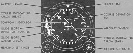
Horizontal Situation Indicator (HSI) The horizontal situation indicator (Fig. 4-44) is a combination of two
instruments, the vertical azimuth card heading indicator and VOR/ILS indicator.
The aircraft heading displayed on the rotating azimuth card under the upper
lubber line is 105°. The course indicating arrow head shown is set to 061°; the
tail indicates the reciprocal, 241°. The course deviation bar operates with a
VOR/LOC navigation receiver to indicate left or right deviations from the course
selected with the course indicating arrow. It moves left or right to indicate
deviation from the centerline in the same manner that the angular movement of a
conventional VOR/LOC needle indicates deviation from course. The desired course
is selected by rotating the course indicating arrow in relation to the azimuth
card by means of the course set knob. This gives you a pictorial presentation.
The fixed aircraft symbol and course deviation bar display the aircraft relative
to the selected course as though you were above the aircraft looking down. The
TO-FROM indicator is a triangular shaped pointer. When the indicator points to
the head of the course arrow, it indicates that the course selected, if properly
intercepted and flown, will take the aircraft to the selected facility, and vice
versa. The glide slope deviation pointer indicates the relation of the aircraft
to the glide slope. When the pointer is below the center position, the aircraft
is above the glide slope and an increased rate of descent is required,
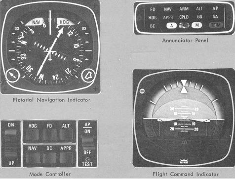
Integrated Flight System (Flight Director System) Further advances in attitude instrumentation combine the gyro horizon with other instruments, thereby reducing the number of separate instruments to which the pilot must devote attention. An integrated flight system consists of electronic components which compute and indicate the aircraft attitude required to attain and maintain a preselected flight condition. "Command" indicators tell the pilot in which direction and how much to change aircraft attitude to achieve the desired result. The computed command indications relieve the pilot of many of the mental calculations required for instrument flight. Figure 4-44. Horizontal situation indicator (HSI).
The flight director/autopilot system described in this paragraph is typical of that installed in some of the more complex general aviation airplanes. The components installed in the instrument panel include the mode controller, flight command indicator, pictorial navigation indicator (horizontal situation indicator), and annunciator panel. These units are illustrated in Figure 4-45. The mode controller contains six pushbutton switches for turning on the flight director and selection of all modes, a switch for autopilot engagement, a trim switch, and a preflight test button. The flight command indicator displays information regarding pitch and roll attitude, pitch and roll commands, and decision height (when used with a radar altimeter). The pictorial navigation indicator displays slaved gyro magnetic heading information, VOR/LOC/RNAV course deviation, and glideslope deviation indications. The annunciator panel displays all vertical and lateral flight director/autopilot modes, including all "armed" modes prior to capture. Simply stated, it tells the pilot when the selected mode has been received and accepted by the system, and if an "armed" mode is selected, when capture has been initiated. It also has integral marker beacon lights and a trim failure warning. Since compact, low cost integrated flight systems are presently available, the future pilot of sophisticated private, business, and executive aircraft as well as the airline and military pilot will be using one of these systems as standard equipment. A flight control guidance system which consists of either an automatic pilot with an approach coupler or a flight director system is required for Category II operations. Figure 4-45. Integrated flight system.
|