| Forces on an Airfoil
Air through which the wing moves creates a force the components of which are referred to as "lift" and "drag" (Fig. 17-8). The resultant force, or "force vector," is resolved trigonometrically into these components of lift and drag, perpendicular and parallel, respectively, to the direction of the undisturbed "relative wind." The lift is the upward force which sustains the airplane in flight. The drag which retards the airplane's forward motion determines the thrust necessary to propel the wing through the air. It is evident, therefore, that the airplane designer is interested in obtaining an airfoil that will produce high lift and low drag over the airplane's flying range of "angles of attack," (the angle of attack being the acute angle between the chord of an airfoil and the direction of the relative wind). The airplane designer's choice of an airfoil is influenced primarily by structural considerations, and onsequently it may not be possible to use an airfoil section that offers the greatest aerodynamic efficiency.
The drag of a wing is a rearward force which acts opposite to the direction of the airplane's forward motion and is made up of two components, the profile drag and the induced drag. The profile drag is the resistance, or skin friction, due to the
viscosity (stickiness) of the air as it passes along the surface of the wing, in
combination with a form drag which is due to the eddying and turbulent wake of
air left behind. Profile drag may be thought of as a pure resistance, such as is
always encountered when an object is pulled through a viscous medium.
Induced drag is the direct result of the aerodynamic force resulting from the downward velocity imparted to the air as discussed previously. It may be said induced drag is the result of creating lift. These forms of drag are more fully explained in later sections of this chapter. The lift and drag of a wing are forces that will vary with the density of the air, the area of the wing, the square of the air velocity, and the angle of attack of the wing as well as other parameters. 
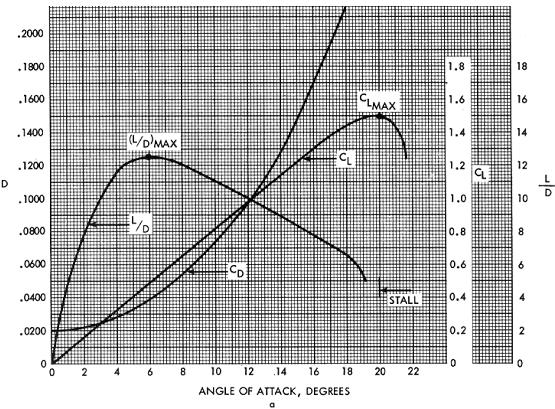
(Fig. 17-10) The manner in which the lift and drag will vary with the air density, wing area, and velocity factors is the same for any airfoil, but the variation of lift and drag with different angles of attack is a definite characteristic of each individual airfoil section. Graphs which show the variation of lift and drag with angle of attack are drawn for each airfoil design (Fig. 17-10). The fact that these graphs give the lift and drag in terms of coefficients should not be confusing. Coefficients are numbers indicating the amount of some change under certain specified conditions, often expressed as a ratio. These coefficients include the mathematical calculations that make it possible to multiply the coefficient by the density, area, and velocity factors corresponding to any particular condition to determine the lift and drag forces in pounds.
|

